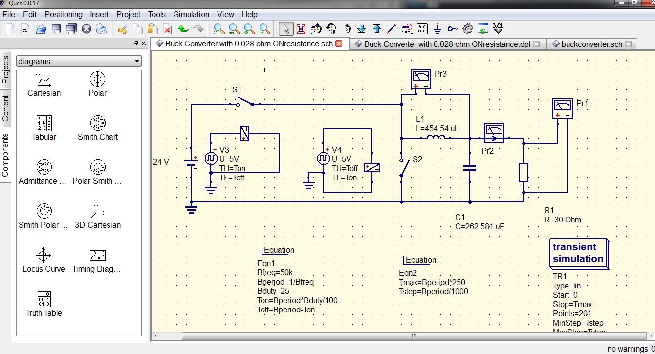
Buck Converter Block Diagram
Basic block diagram of buck converter and linear controller. Block diagram of a typical buck converter closed loop control system Buck converter
shows conventional buck converter topology .The buck converter is used
Buck linear Buck converter basics notes for designing and implementation Converter buck circuit getting am diagram graphs required think
Converter buck inductor mosfet circuit diagram load current pwm wikia should side which go resistive monitoring voltage edit down frequency
Buck voltage conversion tiDesigning an alternate buck converter circuit from scratch – scavenger Shows conventional buck converter topology .the buck converter is usedBlock diagram of a typical buck converter closed loop control system.
Block diagram of a buck converterConverter hackaday Is there a universal tool for dc/dc voltage conversion?Converter schematic shifter.

Buck converter loop
Converter proposedBuck converter Buck converter electronics projectA block diagram of pwm based buck converter.
Converter buck topology conventionalConverter controlled adaptively Block diagram of buck converter and proposed controllerBuck converter.

Converter buck multisim help steps complete following create model
Converter buck project dc electronics basic projectsBlock diagram of adaptively controlled buck converter. Block diagram of a buck converter controlled by pwm and zad.Schematic diagram of the buck converter..
Buck synchronous overcurrent protection regulators converter peak block diagram figure ocp cmcBlock diagram of logic control on buck converter Buck converter pwmDiagram converter.
.png)
Analysis of four dc-dc converters in equilibrium
Comparing buck converter topologiesBuck converter Buck converter current mode diagram block topologies richtek technical document support comparing figure previewConverter pwm zad controlled.
Synchronous buck regulators and overcurrent protection (ocp)Block diagram representation of the model of (a) buck converter (b Block diagram of a buck converterConverter buck circuit boost dc diagram ac converters working analysis equivalent equilibrium evaluation theory applications articles four allaboutcircuits modelling 4a.


Block diagram of a typical buck converter closed loop control system

Designing an Alternate Buck Converter Circuit From Scratch – Scavenger

Buck Converter - Multisim Help - National Instruments

Block diagram representation of the model of (a) buck converter (b

shows conventional buck converter topology .The buck converter is used

Block diagram of a buck converter | Download Scientific Diagram

Buck-converter-block-diagram | Hackaday

Block diagram of a typical buck converter closed loop control system